In Chapters 10 and 11 we studied the dynamics of rigid objects. Part of this current chapter addresses the conditions under which a rigid object is in equilibrium. The term equilibrium implies either that the object is at rest or that its center of mass moves with constant velocity relative to the observer. We deal here only with the former case, in which the object is in static equilibrium. Static equilibrium represents a common situation in engineering practice, and the principles it involves are of special interest to civil engineers, architects, and mechanical engineers. If you are an engineering student, you will undoubtedly take an advanced course in statics in the future.The last section of this chapter deals with how objects deform under load conditions. An elastic object returns to its original shape when the deforming forces are removed. Several elastic constants are defined, each corresponding to a different type of deformation.
12.1 The Conditions for Equilibrium
Consider a single force F acting on a rigid object, as shown in Figure 12.1. The effect of the force depends on the location of its point of application P. If r is the position vector of this point relative to O, the torque associated with the force F about O is given by Equation 11.1: 

Recall from the discussion of the vector product in Section 11.1 that the vector Ʈ is perpendicular to the plane formed by r and F. You can use the right-hand rule to determine the direction of Ʈ as shown in Figure 11.2. Hence, in Figure 12.1Ʈ is directed toward you out of the page.
As you can see from Figure 12.1, the tendency of F to rotate the object about an axis through O depends on the moment arm d, as well as on the magnitude of F. Recall that the magnitude of Ʈ is Fd (see Eq. 10.19). According to Equation 10.21, the net torque on a rigid object will cause it to undergo an angular acceleration.
In the current discussion, we want to look at those rotational situations in which the angular acceleration of a rigid object is zero. Such an object is in rotational equilibrium. Because ∑Ʈ = Ia for rotation about a fixed axis, the necessary condition for rotational equilibrium is that the net torque about any axis must be zero. We now have two necessary conditions for equilibrium of an object:
In the special case of static equilibrium, which is the main subject of this chapter, the object is at rest relative to the observer and so has no linear or angular speed (that is, v CM= 0 and w = 0).
12.1 (a). The unbalanced torques due to the forces in figure 12.2 cause an angular acceleration even though the linear acceleration is zero.
12.2 (b) . Notice that the lines of action of all the forces in figure 12.3 intersect at a common point. Thus, the net torque about this point is zero. This zero value of the net torque is independent of the values of the forces. Because no force has a downward component, there is a net force and the object is not in force equilibrium.
The two vector expressions given by Equations 12.1 and 12.2 are equivalent, in general, to six scalar equations: three from the first condition for equilibrium, and three from the second (corresponding to x, y, and z components). Hence, in a complex system involving several forces acting in various directions, you could be faced with solving a set of equations with many unknowns. Here, we restrict our discussion to situations in which all the forces lie in the xy plane. (Forces whose vector representations are in the same plane are said to be coplanar.) With this restriction, we must deal with only three scalar equations. Two of these come from balancing the forces in the x and y directions. The third comes from the torque equation—namely, that the net torque about a perpendicular axis through any point in the xy plane must be zero. Hence, the two conditions of equilibrium provide the equations
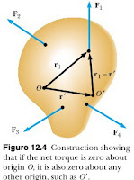
 Where the location of the axis of the torque equation is arbitrary, as we now show. Regardless of the number of forces that are acting, if an object is in translational equilibrium and if the net torque is zero about one axis, then the net torque must also be zero about any other axis. The axis can pass through a point that is inside or outside the boundaries of the object. Consider an object being acted on by several forces such that the resultant force ∑F = F1 + F2 + F3 =… = 0. Figure 12.4 describes this situation (for clarity, only four forces are shown). The point of application of F1 relative to O is specified by the position vector r1. Similarly, the points of application of F2, F3, ... are specified by r2, r3, ... (not shown). The net torque about an axis through O is
 Now consider another arbitrary point O’ having a position vector r’ relative to O. The point of application of F1 relative to O’ is identified by the vector r1 - r’. Like wise, the point of application of F2 relative to O’ is r2 - r’, and so forth. Therefore, the torque about an axis through O’ is
Because the net force is assumed to be zero (given that the object is in translational equilibrium), the last term vanishes, and we see that the torque about an axis through O’ is equal to the torque about an axis through O. Hence, if an object is in translational equilibrium and the net torque is zero about one axis, then the net torque must be zero about any other axis.
12.2 More on the Center of Gravity
We have seen that the point at which a force is applied can be critical in determining how an object responds to that force. For example, two equal-magnitude but oppositely directed forces result in equilibrium if they are applied at the same point on an object. However, if the point of application of one of the forces is moved, so that the two forces no longer act along the same line of action, then the object undergoes an angular acceleration.
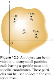
 Whenever we deal with a rigid object, one of the forces we must consider is the gravitational force acting on it, and we must know the point of application of this force. As we learned in Section 9.5, associated with every object is a special point called its center of gravity. All the various gravitational forces acting on all the various mass elements of the object are equivalent to a single gravitational force acting through this point. Thus, to compute the torque due to the gravitational force on an object of mass M, we need only consider the force Mg acting at the center of gravity of the object. How do we find this special point? As we mentioned in Section 9.5, if we assume that g is uniform over the object, then the center of gravity of the object coincides with its center of mass. To see that this is so, consider an object of arbitrary shape lying in the xy plane, as illustrated in Figure 12.5.
 Suppose the object is divided into a large number of particles of masses m1, m2, m3, . . . having coordinates (x1, y1), (x2, y2), (x3, y3), . . . . In Equation 9.28 we defined the x coordinate of the center of mass of such an object to be
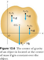
 We use a similar equation to define the y coordinate of the center of mass, replacing each x with its y counterpart. Let us now examine the situation from another point of view by considering the gravitational force exerted on each particle, as shown in Figure 12.6.
 Each particle contributes a torque about the origin equal in magnitude to the particle’s weight mg multiplied by its moment arm. For example, the magnitude of the torque due to the force m1g1 is m1g1x1, where g1 is the value of the gravitational acceleration at the position of the particle of mass m1. We wish to locate the center of gravity, the point at which application of the single gravitational force Mg (where M = m1 + m2 + m3 + … is the total mass of the object) has the same effect on rotation as does the combined effect of all the individual gravitational forces migi. Equating the torque resulting from Mg acting at the center of gravity to the sum of the torques acting on the individual particles gives
This expression accounts for the fact that the value of g can in general vary over the object. If we assume uniform g over the object (as is usually the case), then the g terms cancel and we obtain
Comparing this result with Equation 9.28, we see that the center of gravity is located at the center of mass as long as g is uniform over the entire object. In several examples presented in the next section, we will deal with homogeneous, symmetric objects. The center of gravity for any such object coincides with its geometric center.
12.3 Examples of Rigid Objects in Static Equilibrium
The photograph of the one-bottle wine holder in Figure 12.7 shows one example of a balanced mechanical system that seems to defy gravity. For the system (wine holder plus bottle) to be in equilibrium, the net external force must be zero (see Eq. 12.1) and the net external torque must be zero (see Eq. 12.2). The second condition can be satisfied only when the center of gravity of the system is directly over the support point. When working static equilibrium problems, you must recognize all the external forces acting on the object. Failure to do so results in an incorrect analysis. When analyzing an object in equilibrium under the action of several external forces, use the following procedure.
EXAMPLE..
A seesaw consisting of a uniform board of mass M and length l supports a father and daughter with masses mf and md, respectively, as shown in Figure 12.8. The support (called the fulcrum) is under the center of gravity of the board, the father is a distance d from the center, and thedaughter is a distance l/2 from the center. Determine the magnitude of the upward force n exerted!
Answer:
Solution First note that, in addition to n, the external forces acting on the board are the downward forces exerted by each person and the gravitational force acting on the board. We know that the board’s center of gravity is at its geometric center because we are told that the board is uniform. Because the system is in static equilibrium, the net force on the board is zero. Thus, the upward force n must balance all the downward forces. From ∑Fy = 0 , and defining upward as the positive y direction, we have
(The equation also a∑Fy = 0pplies, but we do not need to consider it because no forces act horizontally on the board).


Tidak ada komentar:
Posting Komentar